


How Does a Micrometre Screw Gauge Work?
A micrometre screw gauge is a precision instrument used in physics and engineering for measuring small linear dimensions, such as thickness or diameter, with high accuracy. It is commonly utilized in laboratories and industry for tasks requiring precise measurement, often up to 0.01 mm or 10 microns.
Principle and Construction of Micrometre Screw Gauge
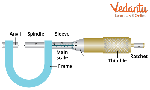
The principle of a screw gauge is based on the precision screw mechanism, which transforms a small linear displacement into a measurable rotational movement on a calibrated scale. The instrument consists of a U-shaped frame, anvil, spindle, main scale (sleeve), thimble, ratchet, and circular scale.
The main scale is engraved on the barrel, while the circular scale is marked on the rotating thimble. The ratchet mechanism ensures a uniform measuring force, thus minimizing errors during measurement.
The micrometer screw gauge is used extensively in experiments related to Units And Measurements Mock Test to develop experimental skills in JEE Main preparation.
Least Count of Micrometre Screw Gauge
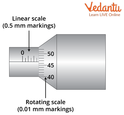
Least count refers to the smallest measurement that can be accurately given by the instrument. For a screw gauge, it is determined from the pitch and the number of divisions on the circular scale.
The pitch is the distance moved by the spindle per complete rotation of the screw, usually 0.5 mm. If the circular scale has 50 divisions, then the least count is obtained using the relation:
Least Count (L.C.) $ = \dfrac{\text{Pitch}}{\text{Number of Divisions on Circular Scale}} $
For example, if Pitch $ = 0.5 $ mm and Number of Divisions $ = 50 $, then
$ \text{L.C.} = \dfrac{0.5}{50} = 0.01 $ mm
Reading the Measurement
Micrometre screw gauge readings are made by combining the main scale reading with the circular scale reading multiplied by the least count. Zero error must also be considered for accuracy.
| Parameter | Typical Value |
|---|---|
| Pitch | 0.5 mm |
| Number of divisions on circular scale | 50 |
| Least count | 0.01 mm |
The general formula for measurement is:
$ \text{Total Reading} = \text{Main Scale Reading} + (\text{Circular Scale Reading} \times \text{Least Count}) - \text{Zero Error} $
This method is essential for measurements requiring high precision, such as in resistance and solid state experiments.
Stepwise Procedure for Taking Reading
The following steps are observed for accurate measurement using a micrometre screw gauge:
- Check and set the initial zero reading
- Place the object between anvil and spindle
- Rotate the ratchet to gently clamp the object
- Note the main scale reading
- Read the circular scale division coinciding with the reference line
- Calculate total reading using the measurement formula
- Apply zero correction if needed
Careful adherence to these steps ensures reliable data for experiments and Kinematics analysis in JEE Main preparation.
Types of Errors and Zero Error Correction
Zero error is the deviation from actual zero position when the anvil and spindle are brought into contact. It can be positive or negative and must be compensated in the final reading. Parallax error, improper tightening, and unclean scales are other possible sources of error.
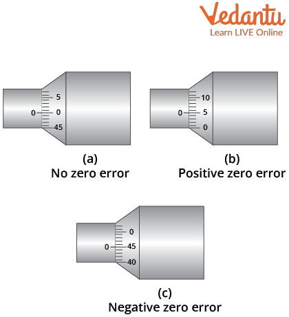
To correct zero error, subtract for positive error and add for negative error as per the correction formula: $ \text{Correct Reading} = \text{Observed Reading} - \text{Zero Error} $.
Applications and Uses of Micrometre Screw Gauge
Micrometre screw gauges are used for measuring the diameter of thin wires, thickness of metal sheets, and dimensions of small machine parts. They are vital in laboratories, manufacturing, and quality control processes.
- Measurement of thin wires for resistance experiments
- Assessment of sheet metal thickness
- Quality control in micro-manufacturing
- Educational demonstrations in physics laboratories
In Thermal Physics experiments, precise thickness measurements ensure reliable material property analysis.
Comparison with Vernier Caliper
The micrometre screw gauge provides higher precision but a lower measuring range compared to the vernier caliper. The typical least count of a screw gauge is 0.01 mm, while that of a vernier caliper is 0.1 mm. Screw gauges are more suitable for very small dimensions.
| Instrument | Least Count |
|---|---|
| Screw Gauge | 0.01 mm |
| Vernier Caliper | 0.1 mm |
Selection between instruments depends on required precision and practical range. For larger objects, the vernier caliper is preferred; for microscopic objects, the screw gauge is superior.
Precautions While Using a Micrometre Screw Gauge
Precautions are necessary to minimize systematic and random errors. The use of the ratchet, regular calibration, and perpendicular sighting are standard requirements for accuracy while performing Electrostatics Mock Test and similar experiments.
- Always use ratchet to prevent excess force
- Clean measuring faces before and after use
- Record zero error prior to measurements
- Take perpendicular readings to avoid parallax
- Handle instrument carefully to prevent damage
Types of Micrometre Screw Gauges
Different types of micrometre screw gauges serve specific measurement tasks: outside micrometres for external dimensions, inside micrometres for internal diameters, depth micrometres for hole depths, and digital micrometres for electronic readings.
Choice of instrument type depends on application needs in both laboratory and industrial settings, supporting precision in topics such as Kinetic Theory Of Gases studies.
Summary of Key Points
- Micrometre screw gauge measures small lengths with up to 0.01 mm accuracy
- Least count is crucial and depends on pitch and number of circular divisions
- Zero error correction must be included in final result
- Instrument type must match the measurement task
- Precision and care are vital for reliable data
FAQs on What Is a Micrometre Screw Gauge?
1. What is a micrometre screw gauge and how does it work?
Micrometre screw gauge is a precision measuring instrument used to measure small dimensions with high accuracy.
Key features include:
- Consists of a calibrated screw and spindle for fine measurements
- Measures thickness or diameter of objects (wires, sheets, etc.)
- Provides readings typically up to 0.01 mm precision
- Main parts are frame, anvil, spindle, sleeve, thimble, ratchet
2. How do you use a micrometre screw gauge step by step?
Using a micrometre screw gauge involves turning the thimble to move the spindle and measuring an object placed between the anvil and spindle.
Steps include:
- Clean the measuring faces (anvil and spindle)
- Place the object to be measured
- Gently rotate the thimble until the object is held firmly
- Use the ratchet to avoid excess force
- Read the main scale (sleeve) and the rotating scale (thimble)
- Add the readings for final measurement
3. What is the least count of a micrometre screw gauge?
Least count of a micrometre screw gauge is the smallest measurement it can accurately read and is usually 0.01 mm.
How to calculate Least Count:
- Least Count = Pitch / Number of divisions on the thimble
- Pitch (distance moved per full turn) is typically 0.5 mm
- If thimble has 50 divisions, Least Count = 0.5 mm / 50 = 0.01 mm
4. What are the main parts of a micrometre screw gauge?
Main parts of a micrometre screw gauge ensure accurate and reliable measurements.
The major parts are:
- Frame: Holds the components together
- Anvil: Fixed surface where the object rests
- Spindle: Movable part that holds the object against the anvil
- Sleeve (Barrel): Marked with main scale
- Thimble: Rotating part used to move the spindle
- Ratchet: Controls pressure applied during measurement
5. What are the uses of a micrometre screw gauge?
Micrometre screw gauges are used for precise measurement of small objects in various fields.
Common uses include:
- Measuring diameter of wires and thin rods
- Measuring thickness of sheets or small components
- Engineering and manufacturing quality checks
- Physics laboratory experiments for length or thickness
6. How do you read the measurement on a micrometre screw gauge?
Reading a micrometre screw gauge involves combining readings from the sleeve (main scale) and thimble (circular scale).
Steps:
- Read the value shown on the main scale (sleeve) up to the last visible mark
- Read the value on the thimble aligning with the reference line
- Add both values for the final reading (e.g., 5.5 mm + 0.23 mm = 5.73 mm)
7. What errors can occur when using a micrometre screw gauge?
Errors in micrometre screw gauge measurements can affect accuracy if not properly addressed.
Common errors include:
- Zero Error: Gauge does not read zero when fully closed
- Parallax Error: Incorrect observation angle
- Excess force: Using more force than needed (avoided by ratchet use)
- Dirt or wear on anvil or spindle surfaces
8. How is zero error determined and corrected in a micrometre screw gauge?
Zero error of a micrometre screw gauge is checked by closing the gauge completely and checking the scale alignment.
Correction steps:
- Close the gauge; observe whether the zero marks align
- If not, note the error value (positive or negative)
- Add or subtract this error from all future readings
- Always record corrected measurements in experiments
9. Why is a ratchet provided in a micrometre screw gauge?
The ratchet in a micrometre screw gauge ensures uniform pressure during measurement.
Reasons for ratchet:
- Prevents excess force that can damage the object
- Gives consistent readings by applying same force each time
- Improves measurement accuracy and prevents errors
It is especially helpful in laboratory exams and practical work.
10. What is the difference between a micrometre screw gauge and a vernier caliper?
Micrometre screw gauge and vernier caliper are both precision instruments but differ in application and precision.
Differences include:
- Micrometre gauge measures smaller objects (accuracy to 0.01 mm), suitable for wires and thin sheets
- Vernier caliper measures large objects (accuracy to 0.1 mm), suitable for external/internal dimensions and depths
- Micrometre uses screw mechanism, vernier uses sliding scale